


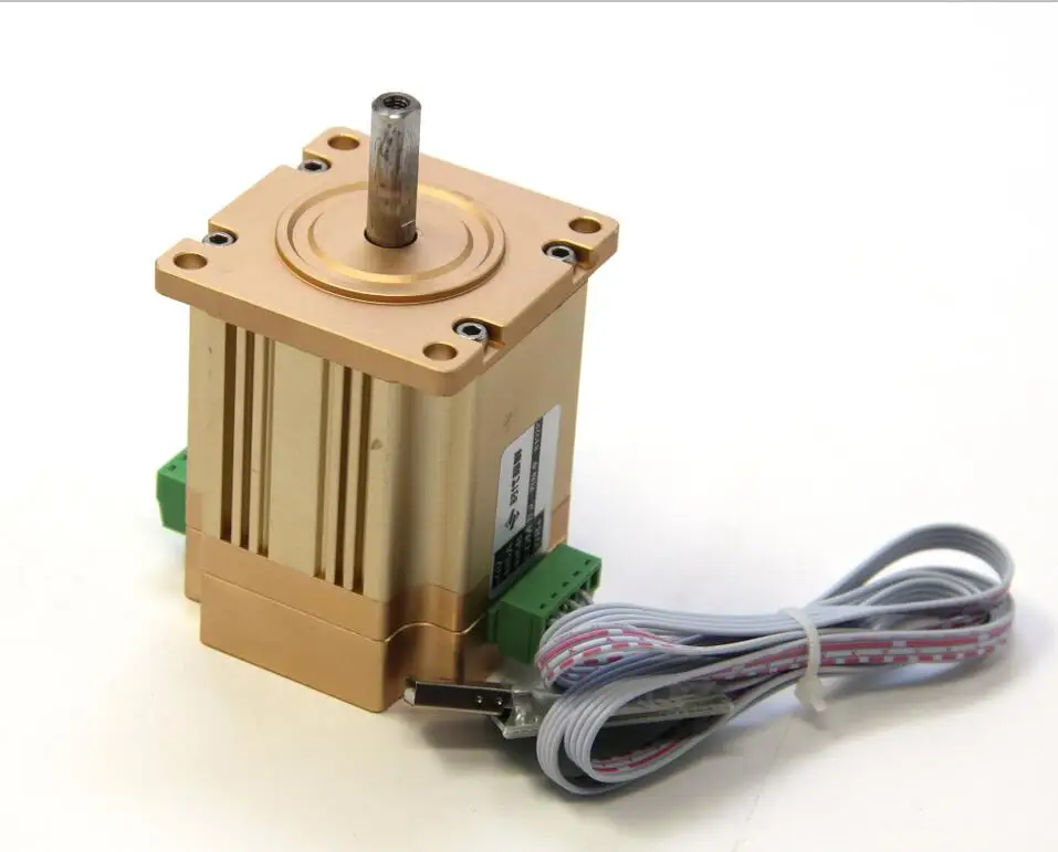
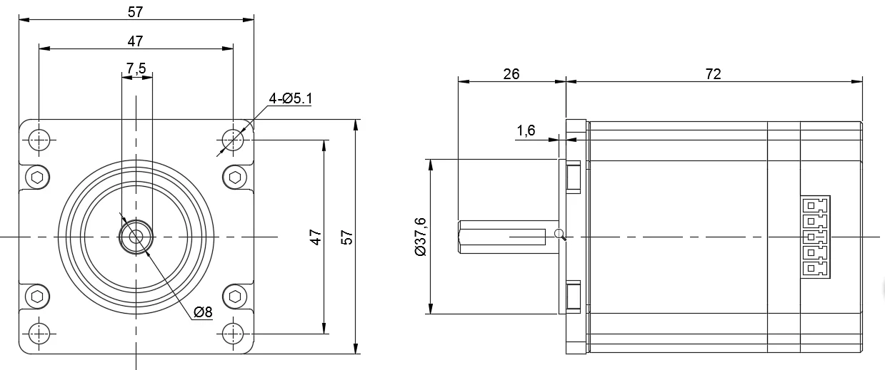
Motor Details
|
model number
|
57D2R1010-SJ0 |
|||
|
|
|
24VDC±10% |
||
|
|
4.4A |
|||
|
|
torque
|
0.96NM |
||
|
rated speed |
1000RPM |
|||
|
|
1500RPM |
|||
|
power |
100W |
|||
|
|
Single coil 15-bit magnetoelectric encoder (single coil 32768 pulse) |
|||
|
Cooling mod |
|
|||
|
|
0.56KG |
|||
|
Position control mode |
Maximum input pulse frequency |
500KHz |
||
|
|
Pulse command mod |
pulse+direction, A+B |
||
|
|
Pulse command mod |
The set range1~65535 1~65535 |
||
|
|
Position sampling frequency |
2KHz |
|
|
|
Locked-rotor alarm |
||
|
|
RS485(modbusRTU 19200,8,N,1) |
||
|
|
|
0~40° |
|
|
work under the allowed highesttemperature |
85° |
||
|
humidity |
5~95% |
||
Driver specification:
(1)Power and control signal interface
|
Terminal serial number |
|
function |
|
1 |
+24V |
Positive pole of dc power supply, +24V.Positive and negative connection will directly short circuit the power supply, may also damage the driver |
|
2 |
GND |
Direct current source.Positive and negative connection will directly short circuit the power supply, may also damage the driver |
|
3 |
PU+ (+5V) |
Pulse control signal: the pulse rising edge is effective;PU- normally 3.3 ~ 5V at high voltage and 0 ~ 0.5v at low voltage. To reliably respond to pulse signals, the pulse width should be greater than 1.2 microns.Series resistance is required if +12V or +24V is used.
|
|
4 |
PU- (PU) |
|
|
5 |
DIR+ (+5V) |
Direction signal: high/low level signal. In order to ensure reliable commutation of motor, direction signal should precede pulse signal At least five microns are established.DIR- 4 ~ 5V at high voltage and 0 ~ 0.5v at low voltage.
|
|
6 |
DIR- (DIR) |
Terminal number: facing the terminal, the left side is the first.
AIM series adopts differential interface circuit applicable to differential signal, single-terminal common negative and common positive interfaces, built-in high-speed optocoupler, allowing the reception of long line driver, collector open circuit and PNP output circuit signals.
(2)Communication and alarm interface
|
name
|
function
|
|
WR+ |
Alarm signal output, internal optical coupling NPN output.Normal for high resistance state, alarm and COM conduction. |
|
COM |
Alarm signal and 485 power supply common ground. |
|
485B |
485Communication – |
|
485A |
485Communication + |
|
485_5V |
485Communication5Vpower supply,External power supply is required. This power supply is supplied by the controller. |
(3)Status indication and alarm
After starting up, the red light and green light will be on once to check whether the LED is working normally.Then the green light turns on and the red light turns off as normal.If the alarm state is encountered, the reason can be determined by red flashing, or the alarm code can be read by modbus.
|
Alarm code |
Red lights flashing |
The alarm reason |
report this to the police |
|
0x14 |
One long flash and four short flashes |
Locked-rotor alarm |
Downtime |
Note: blockage alarm, blockage time can be set, please refer to the register for details.
(4) Typical wiring diagram


PLS SEND US INQUIRY ABOUT MORE INFORMATION AND DISCOUNTS!!


Reviews
There are no reviews yet.